Gas Filter – Heat Exchanger type PFI-C
- Home
- About us
- Activities
- Products

 Safety relief valves
Safety relief valve for air type SVN-N
Diaphragm Safety relief valve type SVM-N
Diaphragm Safety relief valve type SVM-P
Safety relief valve for LPG type SVN
Safety relief valve type SVON
Safety relief valve type UTS-101
Safety relief valve type SVOP-K
Pilot-operated safety relief valve type SVN-P
Pilot-operated safety relief valve type SVP-P
- Safety shut-off valve
- Pressure relief valve manifold
 Excess flow valve
 Pneumatic gate valve
- Pneumatic shut-off valve
 Solenoid valve
 Water Nozzles
 Gas Filters
 Gear Pumps
- Service program
- Sales program (valves for steam,
water, natural gas, LPG and
other media) - Projects
- Products
- Activities
- References
- Contact


Products
gas and oil installations, MEBA measurings...

Service program
service, calibration, CNC turning, milling...

Sales program
Leser, Danfoss, Bopp&Reuther...


Contact information
SPECIJALNA OPREMA - Lučko d.o.o.
Dolenica 20, Donji Stupnik, 10250 Lučko
ZAGREB, HRVATSKA
POSLOVNA JEDINICA JUŽNA HRVATSKA
Ivana Pavla II 19a, 21212 Kaštel Sućurac,
SPLIT, HRVATSKA
Email: specijalna-oprema@specijalna-oprema.hr
Phone: +385 (0)1 653 0671, +385 (0)1 653 0677
Fax: +385 (0)1 653 0680
The PDF document below provides detailed information for this product

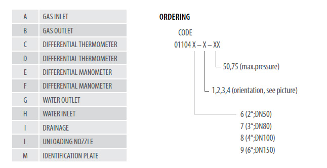
DN 2” –6”(50 – 150)
PN 63, 100
ANSI 300, 600 lb
pmax 50, 75 bar
Temperature
water (inlet/outlet) 90°C / 80°C
gas (inlet/outlet) 5°C / 10°C
medium natural gas, LPG
connections EN1092, DIN2633, ANSI B 16.5
APPLICATION
In gas pressure regulating stations in consequence of gas expansion, a considerable gas temperature drop takes place. In order to maintain failure-free action of it is necessary to increase gas temperature prior to regulation to assure a gas temperature within +5 to + 10°C after regulation. One of the most commonly used methods of heating natural gas in pressure regulating stations is the use of heat exchangers with hot fluid used as the heating medium.
DESIGN FEATURES
The heating medium temperature in the heat exchanger is controlled depending on gas temperature downstream the regulating unit, while internal mounting of the heating fluid circulation pump improves heat transfer and control accuracy.
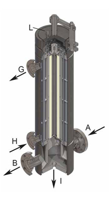
Cold gas flows through the inlet in to the large number of small tubes. After being heated, gas flows through the tube side the outlet into the pipeline system. The heating medium flows through a number of baffles, leading it round the small tubes inside heater. The tubes are welded into a mesh bottom, designed (calculated) appropriately to the gas pressure and capacity.
The tube side of the heat exchanger features connector pipes for draining condensate.
PFI heat exchanger has got an unloading nozzle for gas venting into the atmosphere. On the top of the heater shell there is a connection for safety valve installment, so in case of circulation system failure, or breach of gas into the heat medium, the heating medium may be immediately relieved.
ON REQUEST:
- Shell thermo isolated, thickness 80mm
- Installed safety relief valve
- Differential manometer
- Differential thermometer
-ASME certification
APPLIED STANDARDS, CODES & DIRECTIVES
EN 13445 „Unfired pressure vessels“
97/23 EC (PED) “Pressure equipment directive”
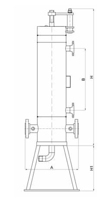
| CONNECTION | SIZE | |||
|---|---|---|---|---|
| 2” (DN50) | 3” (DN80) | 4” (DN100) | 6” (DN150) | |
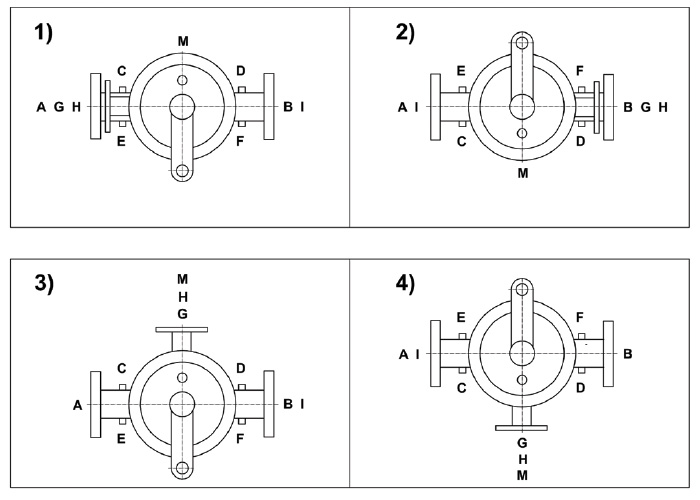
| GAS inlet/outlet (A,B) | 2” (DN50) | 3” (DN80) | 4” (DN100) | 6” (DN150) |
| DIF. THERMOMETER (C,D) | 3/4” | 3/4” | 3/4” | 3/4” |
| DIF.MANOMETER (E,F) | 1/2” | 1/2” | 1/2” | 1/2” |
| WATER inlet/outlet (G,H) | 1 1/2“(DN40) | 2” (DN50) | 3” (DN80) | 4” (DN100) |
| DRAINAGE (I) | 3/4” | 1” | 1” | 1” |
| UNLOADING NOZZLE (L) | 1/2” | 1/2” | 1/2” | 1/2” |
| A (mm) | 470 | 600 | 730 | 900 |
| B (mm) | 550 | 700 | 850 | 1000 |
| H (mm) | 1220 | 1550 | 1880 | 2300 |
| H1 | ON REQUEST | |||
Orientation of filter-exchanger